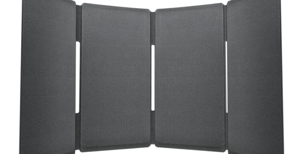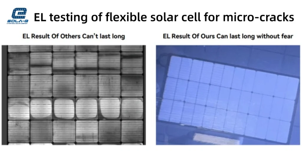
Portable solar panels rarely operate under perfect sunlight all day. Irradiance changes with the time of day, cloud cover, season, location, and panel orientation. For buyers developing portable power stations, campervan systems, emergency kits, or other mobile-energy products, rated wattage is therefore only one part of the evaluation.
To examine how output changes as available light decreases, Sola-E tested one UT60H 60 W foldable solar panel at three controlled irradiance levels: approximately 1,000, 800, and 700 W/m².
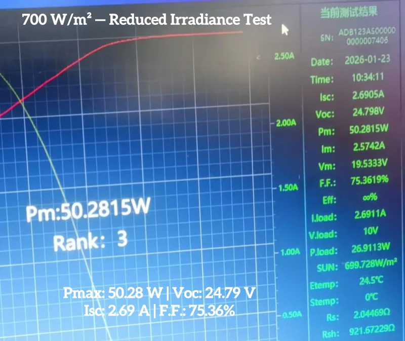
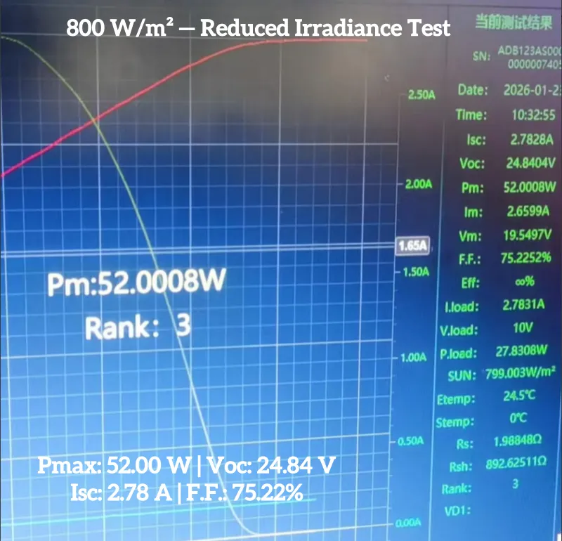
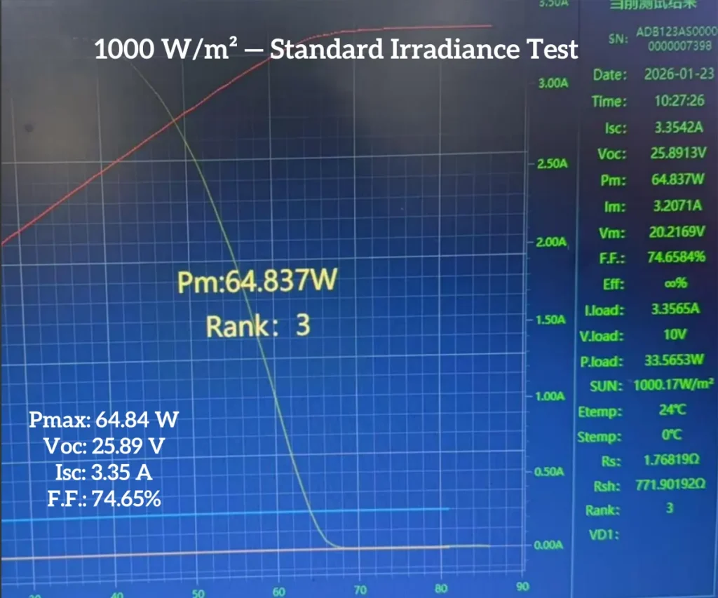
The sample produced 64.84 W at approximately 1,000 W/m². At the two reduced irradiance levels, it produced 52.00 W and 50.28 W respectively. The results provide a useful sample-level view of electrical behavior under controlled, uniformly reduced light.
Important: This was a controlled solar-simulator test on one sample. It was not an outdoor energy-yield study, a partial-shading test, or a guarantee of output in all field conditions. I-V curve measurement is commonly used to characterize the voltage-current response of photovoltaic devices under natural or simulated sunlight. Measurement procedures are described in IEC 60904-1.
Product and Test Overview
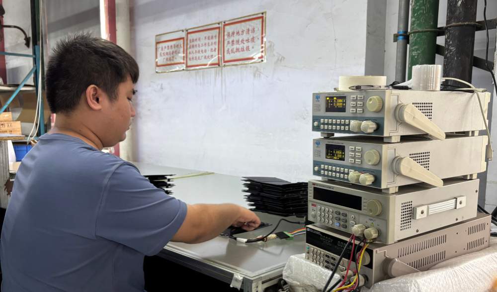
Electrical performance verification is part of our internal quality-control process. Depending on the project and validation stage, panels may be checked for voltage, current, output stability and I-V performance using the applicable test equipment.
| Item | Test sample details |
|---|---|
| Product | ETFE foldable solar panel |
| Model | UT60H |
| Rated maximum power | 60 W |
| Cell technology | A-grade HPBC solar cells |
| Nominal cell efficiency | 25.4% |
| Test equipment | Class AAA solar simulator |
| Module temperature during test | 24-25°C |
| Air mass | AM 1.5 |
| Irradiance levels | 1,000.17, 799.0, and 699.7 W/m² |
The 25.4% figure refers to the nominal efficiency of the solar cells, not the finished module efficiency. Finished-panel efficiency also depends on active cell area, interconnection losses, encapsulation, spacing, and the panel’s overall dimensions.
Electrical Test Results
| Irradiance | Maximum power (Pmax) | Open-circuit voltage (Voc) | Short-circuit current (Isc) | Voltage at Pmax (Vmp) | Current at Pmax (Imp) | Fill factor |
|---|---|---|---|---|---|---|
| 1,000.17 W/m² | 64.837 W | 25.89 V | 3.35 A | 20.21 V | 3.20 A | 74.65% |
| 799.0 W/m² | 52.00 W | 24.84 V | 2.78 A | 19.55 V | 2.66 A | 75.22% |
| 699.7 W/m² | 50.28 W | 24.79 V | 2.69 A | 19.36 V | 2.60 A | 75.36% |
At the highest test level, the sample exceeded its 60 W nameplate rating by 4.84 W, or approximately 8.1%. This is a positive power tolerance result for the tested unit under the stated laboratory conditions.
What Changed as Irradiance Decreased?
1. Power output decreased, but voltage remained comparatively stable
When irradiance was reduced from approximately 1,000 to 799 W/m², maximum power decreased from 64.84 W to 52.00 W. At approximately 700 W/m², the measured maximum power was 50.28 W.
Across the three measurements, open-circuit voltage remained between 24.79 and 25.89 V, while voltage at maximum power remained between 19.36 and 20.21 V.
This pattern is useful when evaluating a panel for a charge controller or portable power station. However, compatibility cannot be confirmed from the panel wattage alone. The device’s photovoltaic input voltage range, current limit, connector, polarity, and MPPT operating window must also be checked.
2. Current showed more variation than voltage
Solar-module current normally responds more strongly to changes in irradiance than voltage. In this test, short-circuit current changed from 3.35 A at the highest irradiance to 2.78 A at approximately 800 W/m² and 2.69 A at approximately 700 W/m².
The same general behavior appeared at the maximum power point: current decreased while operating voltage stayed within a relatively narrow range.
3. Fill factor remained consistent
Fill factor was 74.65%, 75.22%, and 75.36% across the three measurements. Fill factor describes the relationship between the maximum-power point and the product of open-circuit voltage and short-circuit current. Consistency across a controlled test series can help engineers compare the electrical response of a particular sample at different irradiance settings.
It should not, by itself, be treated as proof of field durability, shading tolerance, or long-term energy yield.
Rated Power Is Not the Same as Daily Energy Yield
A 60 W rating describes power under specified test conditions. It does not mean that the panel will continuously deliver 60 W outdoors.
Actual charging performance can be affected by:
- solar irradiance and weather;
- panel angle and orientation;
- cell and ambient temperature;
- partial shading from trees, vehicles, cables, or nearby objects;
- contamination, dust, and surface condition;
- cable length and electrical losses;
- charge-controller conversion efficiency;
- battery state of charge and device input limits.
For an OEM project, the more useful question is not simply, “What is the panel’s rated wattage?” It is, “Does the complete panel-and-controller system deliver the required energy within the available area and operating conditions?”
What This Test Does—and Does Not—Show
The test shows the electrical output of one UT60H sample under three uniform irradiance settings in a controlled environment. It provides I-V measurement data that can be used for sample verification and preliminary system matching.
The test does not reproduce:
- localized or moving shadows across individual cells;
- hot outdoor module temperatures;
- changes in sun angle during the day;
- repeated folding or mechanical aging;
- rain, dust, salt mist, or long-term UV exposure;
- accumulated watt-hours over a full day;
- performance variation across a production lot.
These factors require separate test methods. In particular, uniformly reducing irradiance in a solar simulator is not equivalent to partially shading a module. Partial shading can create electrical mismatch and may produce a very different I-V curve.
What OEM Buyers Should Request from a Supplier
When comparing foldable solar panels, ask for evidence that matches the intended application rather than relying only on a nameplate wattage. Useful information includes:
- I-V test data at the rated condition;
- voltage and current at the maximum power point;
- power-tolerance criteria and inspection method;
- cell type and traceable cell specification;
- panel dimensions, weight, and folded size;
- output connector, polarity, cable specification, and controller compatibility;
- construction details such as the front layer, encapsulation, backing, hinges, and edge protection;
- relevant mechanical and environmental test reports;
- batch sampling and traceability controls;
- application-specific testing for heat, repeated folding, water exposure, or partial shading when required.
Engineering Takeaway
Under the stated laboratory conditions, the tested UT60H sample passed the 60 W rated-power check at approximately 1,000 W/m² and maintained a comparatively narrow operating-voltage range as irradiance was reduced. The measurements offer a useful reference for early-stage electrical evaluation.
They should still be interpreted as sample-specific laboratory results. Final product selection should consider the complete charging system, intended environment, mechanical design, and production-validation requirements.
Frequently Asked Questions
Q1: Will a 60 W foldable solar panel always produce 60 W outdoors?
No. Rated power is measured under defined test conditions. Outdoor output changes with irradiance, temperature, panel orientation, shading, cable losses, controller efficiency, and the connected device.
Q2: Does lower irradiance affect voltage and current equally?
No. Current generally changes more directly with irradiance, while voltage often remains within a narrower range. The exact response depends on the cells, circuit design, temperature, and test conditions.
Q3: Does this test prove performance in cloudy weather?
It provides controlled data at lower uniform irradiance, which is relevant to weaker-light conditions. It does not fully reproduce real clouds, fluctuating sunlight, diffuse light, or partial shading outdoors.
Q4: Can this panel be connected to any portable power station?
Not automatically. The panel’s Voc, Vmp, Isc, Imp, connector type, polarity, and cable configuration must fall within the power station’s PV input limits.
Q5: Can the same testing be used for a custom OEM panel?
Yes. I-V testing under defined irradiance and temperature conditions can be included in sample validation or production quality control. The test plan should be agreed according to the product specification and application.
Developing a Custom Foldable Solar Panel?
Sola-E supports OEM and ODM development for portable solar charging, campervan and RV systems, outdoor equipment, emergency power products, and other space- or weight-constrained applications.
To evaluate feasibility, send us your:
- Available panel area and folded-size limit
- Target power and system voltage
- Device or controller PV input specification
- Weight and thickness targets
- Cable, connector, and polarity requirements
- Operating environment
- Expected annual volume
- Required certifications or validation tests
Our engineering team can review the available cell area, electrical configuration, material stack, mechanical layout, and manufacturing feasibility before the specification is finalized.
Sam | Solar Application Specialist
With over 10 years of experience in the photovoltaic manufacturing industry, Sam specializes in risk control and application engineering for portable battery chargers and marine solar panel solutions. He helps OEMs and distributors bridge the gap between technical specs and real-world performance.