We’ve seen it countless times: a flexible panel works perfectly in the warehouse, but fails three months after being glued to an RV roof. Why? The gap between ‘laboratory bending’ and ‘real-world installation’ is where most warranties die.
The gap between a flexible solar panel’s theoretical performance and its real-world lifespan is almost always determined during the first 60 minutes of installation. While buyers choose these panels for their adaptability to curved surfaces like RV roofs and yacht Biminis, most are unaware that directional stress is a silent killer. In this guide, we break down why traditional installation methods often lead to premature failure and how a ‘tolerance-first’ design can protect your investment from irreversible structural damage.
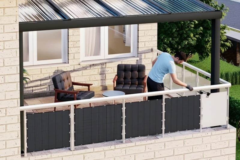
Installation Is Rarely Ideal
In real-world applications, flexible solar panels are often mounted:
- On curved or irregular surfaces
- With varying degrees of tension
- By users with different levels of technical experience
- In temporary or semi-permanent configurations
Even when installation guidelines are provided, actual conditions are rarely controlled.
This variability is not misuse — it is reality. Explore our full range of [Flexible Solar Panels] here.
The Risk of Directional Stress
Many flexible solar panels are designed to bend primarily in one direction, within a limited angle range.
When installation forces deviate from this expected direction — even slightly — stress can concentrate in specific areas of the panel structure.
Over time, this may lead to:
- Internal structural fatigue
- Localized damage
- Performance degradation without visible surface failure
For channels, these issues are especially difficult to manage once panels are installed.
Section 1: The “Silent Killer” — Localized Pressure and Torsion
While “bending radius” is a popular spec, it doesn’t cover the most common cause of installation damage: Localized Point Pressure.
During a non-professional installation, a technician might accidentally lean their knee or elbow on the center of a panel while reaching for a junction box. On a standard flexible panel, this creates a high-pressure “point load” that can cause micro-cracks in the silicon wafers. Even if the panel functions immediately after, these cracks expand over time as the weather changes.
Furthermore, Torsion (twisting)—where one corner of the panel is pulled in a different direction than the others—is far more damaging than a simple, clean arc. By implementing a multi-directional stress-relief grid, our panels are engineered to redistribute this uneven pressure across a wider surface area, significantly lowering the “failure-per-install” rate for high-volume OEM projects.
Design Approach: Tolerance for Multi-Directional Bending
Our flexible solar panels are designed to tolerate 360-degree multi-directional bending, not to encourage extreme installation, but to reduce sensitivity to installation variation. Our USF-110H 110W Flexible Solar Panel utilizes the exact ETFE encapsulation and EL testing standards discussed above to minimize installation stress risks.
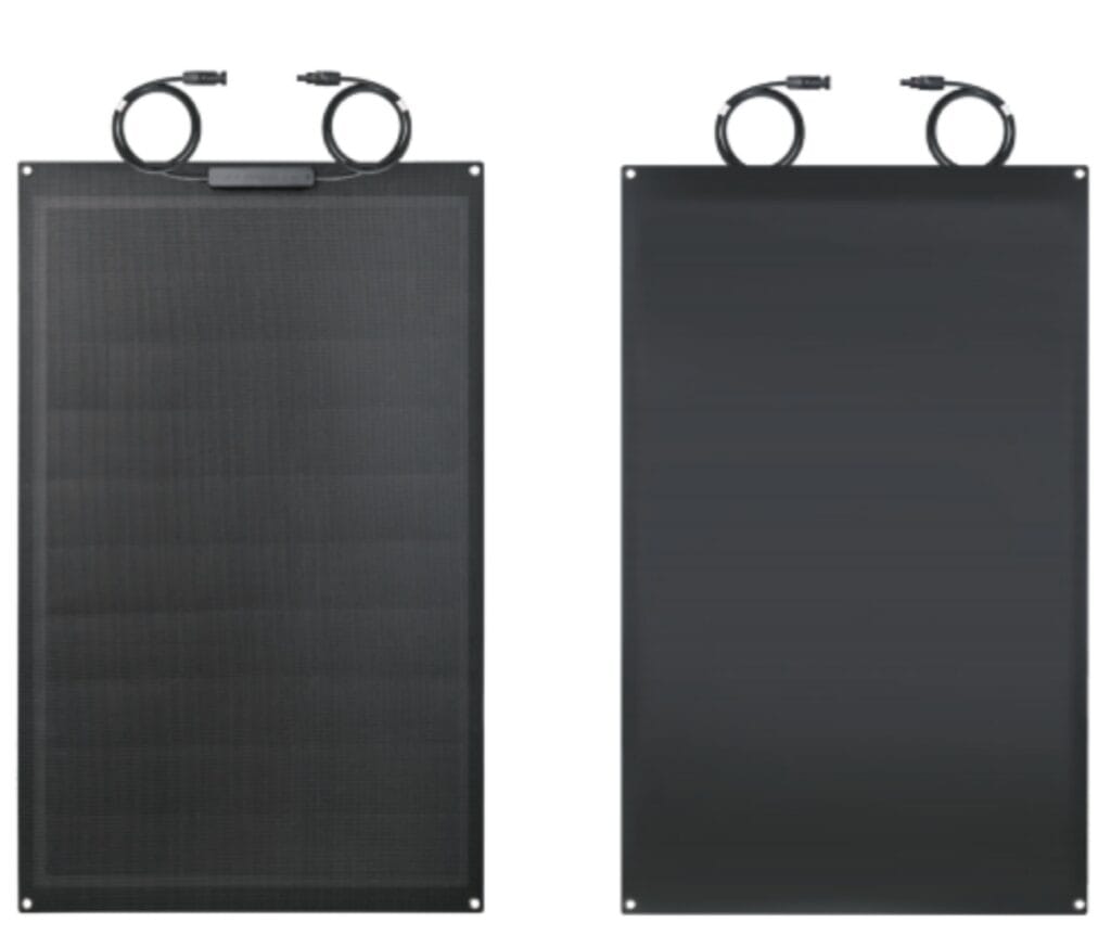
This structural flexibility allows the panel to adapt more naturally to real mounting conditions, including:
- Changes in surface curvature
- Minor alignment deviations
- Uneven stress distribution during installation
The objective is not unlimited bending, but greater tolerance to non-ideal mounting behavior.
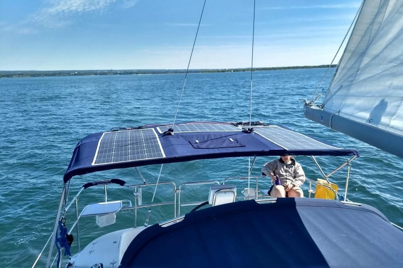
Section 2: Dynamic Surfaces — Marine vs. RV Installation
In the field, flexible solar panels are rarely mounted on static, flat surfaces. For our channel partners, understanding the environment is as critical as the panel itself.
Marine Applications (Bimini Tops): On a boat, panels are often integrated into canvas or Bimini tops. These surfaces are dynamic; they vibrate with engine resonance and flutter under high-wind conditions. This constant micro-vibration can cause “fatigue failure” in standard panels, leading to delamination. Our design accounts for this by utilizing a high-tenacity polymer encapsulation that absorbs these micro-movements rather than resisting them rigidly.
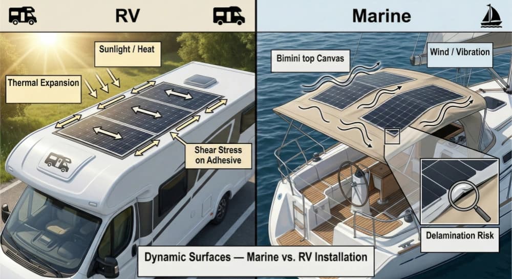
RV & Overland Applications: Mounting a panel to an aluminum or fiberglass vehicle roof introduces the challenge of Differential Thermal Expansion. As the sun beats down, the metal roof expands at a different rate than the solar panel. If the mounting adhesive is too rigid, the resulting shear stress can pull the internal cells apart. We recommend specific “floating” or “gap-bridging” adhesive patterns to allow the panel and the roof to move independently, preserving the circuit integrity over thousands of thermal cycles.
Why This Matters for Channel Partners
Installation-related failures are among the most challenging issues for distributors and retailers because:
- They often occur after irreversible mounting
- Responsibility is difficult to define
Removal or replacement may not be straightforward
- By increasing structural tolerance to installation variability, this design approach helps reduce:
- Disputes related to installation damage
- Ambiguous after-sales cases
- Channel exposure to irreversible outcomes
In flexible solar applications, predictability is more valuable than theoretical flexibility limits.
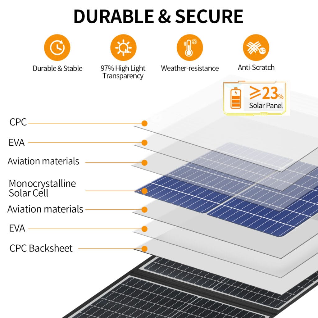
Section 3: Advanced Encapsulation — Building Resilience at the Atomic Level
While most “flexible” panels in the market rely on standard PET films, our manufacturing process utilizes a multi-layer ETFE (Ethylene Tetrafluoroethylene) encapsulation. This isn’t just about UV resistance; it’s about inter-layer bonding strength.
Through a proprietary high-temperature vacuum lamination process, we ensure that the polymer layers and the solar cells become a single, cohesive unit. This prevents “internal delamination”—a common failure where the layers peel apart due to the stresses of bending or rapid temperature changes. By controlling the lamination pressure at every square centimeter, we eliminate the microscopic air pockets that typically lead to hot spots and circuit failure in cheaper alternatives.
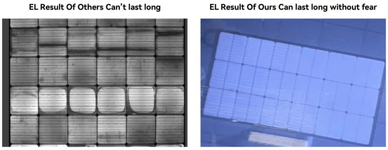
Section 4: Quality Control: The EL Testing (Electroluminescence) Standard
To ensure every panel leaving our facility is truly “installation-ready,” we implement a mandatory Dual-Stage EL Testing protocol.
- Stage 1 (Post-Stringing): We scan the cells immediately after they are connected to detect invisible micro-cracks that might have occurred during the stringing process.
- Stage 2 (Post-Lamination): We perform a final EL scan while the panel is under a specific mechanical load.
This rigorous testing ensures that the “flexibility” we promise isn’t just a theoretical limit on a spec sheet, but a verified structural capability. For our channel partners, this means the panels you receive have already survived more stress in our factory than they are likely to encounter in a standard professional installation.
Section 5: Managing Channel Risk — A Guide for Distributors
For B2B distributors, the cost of a single “failed” panel isn’t just the hardware; it’s the labor, the shipping, and the potential damage to your reputation. To minimize these “gray area” warranty claims, we advise our partners to implement a Pre-Installation Verification (PIV) protocol.
- Dry-Fit Testing: Always test the voltage (Voc) and current (Isc) while the panel is flat on the ground before any adhesive is applied.
- Surface Evaluation: Ensure the mounting surface does not have “high spots” or sharp fasteners that could create pressure points under the panel once vacuum-sealed or glued.
- Boundary Definition: Clearly define for the end-user that “flexible” does not mean “indestructible.”
By shifting the conversation from “How much can it bend?” to “How safely can it be mounted?”, distributors can set realistic expectations and reduce ambiguous after-sales disputes. Our “tolerance-first” engineering is designed to be your first line of defense against these operational risks.
Designed for Real Surfaces, Not Perfect Scenarios
Flexible panels are selected precisely because real surfaces are not perfect.
Our focus is to ensure that reasonable installation variation does not immediately translate into structural risk — allowing channel partners to operate within clearer and more manageable boundaries.
Sam | Solar Application Specialist
With over 10 years of experience in the photovoltaic manufacturing industry, Sam specializes in risk control and application engineering for portable battery chargers and marine solar panel solutions. He helps OEMs and distributors bridge the gap between technical specs and real-world performance.
FAQ
Q1: Is the bending radius (e.g., 30°) the most important metric for installation safety?
A: Not necessarily. In laboratory settings, panels are bent along a perfect axis. However, in B2B applications—such as mounting on a 3D-curved boat deck—the panel often faces torsion (twisting) rather than a simple bend. Our engineering focuses on multi-directional tolerance. This means our cells and busbars are designed to handle the uneven manual pressure applied during installation, which is far more common than exceeding the theoretical bending limit.
Q2: Can micro-cracks occur if the panel looks perfectly fine after mounting?
A: Yes, and this is the primary cause of post-installation disputes. Standard flexible panels use fragile cell interconnects that can snap under localized tension, leading to ‘invisible’ power loss. We’ve redesigned our internal circuit with a denser, redundant interconnect system. Our goal is to ensure that even if a panel is handled roughly during a high-stakes OEM project, the electrical integrity remains intact, preventing the costly ‘installed-then-removed’ cycle.
Looking for a Reliable OEM Partner?
Understanding these risks is the first step. View our [360-degree flexible solar panel series] for high-tolerance applications.
Preventing them requires a manufacturing partner who designs for reality, not just for the spec sheet. We have documented our complete approach to risk control, warranty boundaries, and partner support here: